Overview
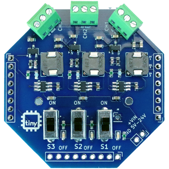
tinyGlow is an expansion HAT for the tinyCore platform that drives LED strips. Lots of them. It has three output channels, and each one gets its own power regulator, its own on/off switch, and its own data pin from the tinyCore. Stack it on, screw your strips into the terminals, and you’re making things glow.
Each channel can push up to 4 amps. That’s a lot of LEDs. A single tinyCore pin can source a few milliamps, so without a board like this you’d be hand-wiring a separate power supply to every strip. tinyGlow does that part for you.
The board was designed by Alden Reeves. His name is on the back, go look.
Okay, but first:
How does an addressable LED actually work?
Section titled “How does an addressable LED actually work?”The strips we’re talking about here use WS2812B LEDs (you’ll also hear them called NeoPixels). Every single LED on the strip has a tiny controller chip built into it, right alongside the red, green, and blue dies.
They’re wired in a chain. Your tinyCore sends a stream of color data down one wire. The first LED grabs the first 24 bits (8 for green, 8 for red, 8 for blue), keeps them, and passes everything else along to the next LED. That one grabs the next 24 bits and passes on the rest. And so on, all the way down the strip.
That’s the whole trick. One data pin, as many LEDs as you want, and every one of them can be a different color.
The timing on that data line is extremely tight (we’re talking fractions of a microsecond), so you never write it by hand. A library like FastLED handles it. You just say “LED 4 is purple” and call show().
What’s on the Board
Section titled “What’s on the Board”| Component | What It Does |
|---|---|
| 3x output channels (CH1, CH2, CH3) | Screw terminals for your strips, labeled V / SIG / G |
| 3x buck regulators | One per channel, so each strip gets its own clean power, up to 4A |
| 3x slide switches (S1, S2, S3) | Turn each channel’s power on or off |
| Status LEDs | Show which channels are powered |
| +VIN terminal | External power input, 5V to 24V |
| J8 pad | Optional wire that powers the HAT from the tinyCore’s USB (more on this below) |
Pin assignments live on the Pinouts page.
What You’ll Need
Section titled “What You’ll Need”| Item | Required For |
|---|---|
| tinyCore ESP32-S3 | Everything |
| tinyGlow HAT | Everything |
| USB-C cable | Programming and power |
| Soldering iron + solder | Header and terminal assembly |
| WS2812B LED strip | Something to glow |
| Small flathead screwdriver | Screw terminals |
| Short piece of wire | Only if you want USB power (J8) |
| 5V to 24V power supply | Only for long strips or high brightness |
1. Assembling the HAT
Section titled “1. Assembling the HAT”Here’s everything in the bag: the tinyGlow board, two 8-pin male headers, three 3-pin screw terminals (one for each channel), and one 2-pin screw terminal for power input.
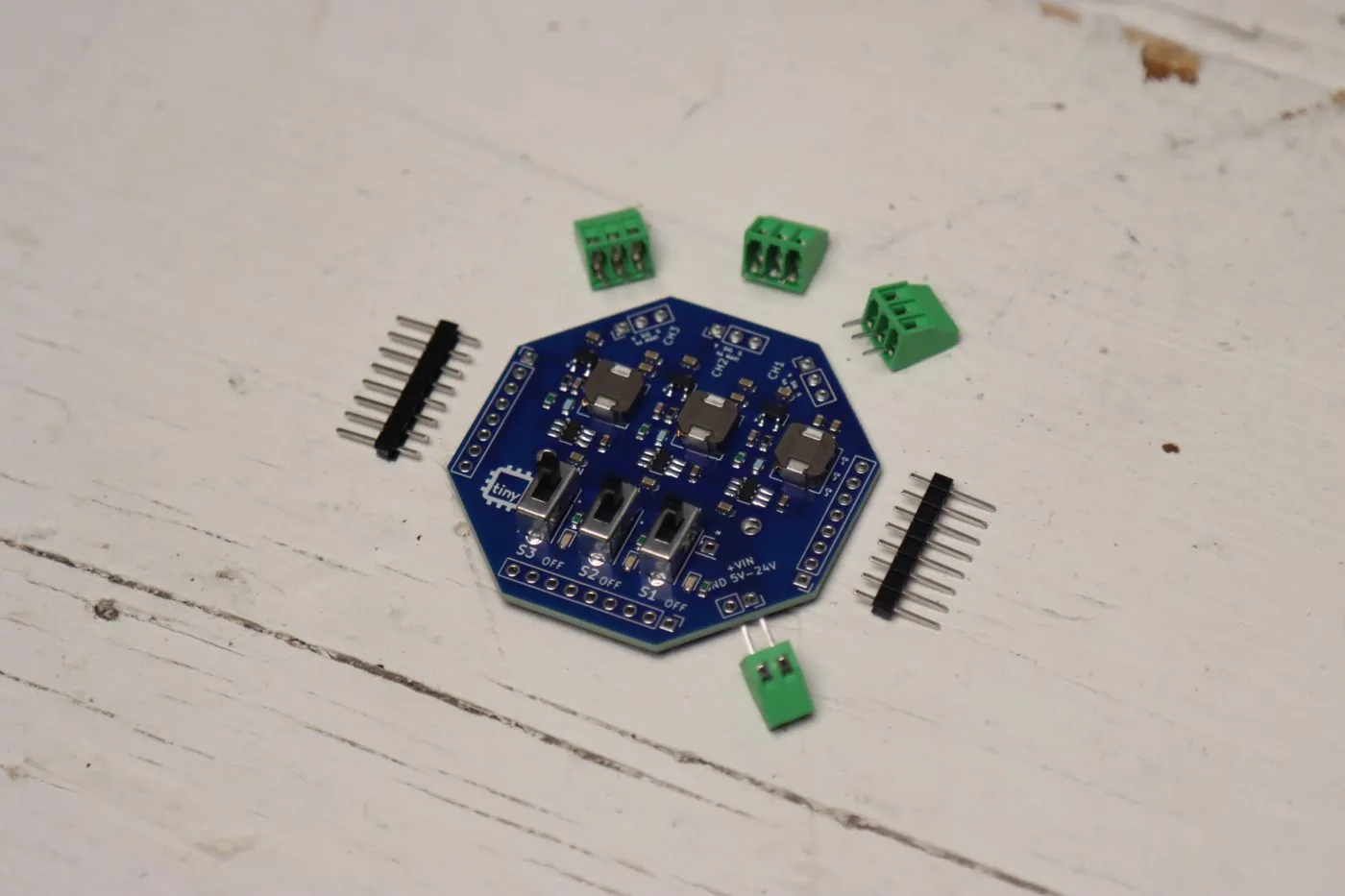
The male headers go on the left and right edges. The row of holes along the bottom edge (by the switches) stays empty, tinyGlow doesn’t need those pins.
-
Insert the two male headers into the tinyGlow from the bottom side of the board, so the long pins point downward (these plug into the tinyCore) and the short pins poke through the top where you’ll solder them.
-
Before you solder anything, seat the long pins loosely into your tinyCore and set the tinyGlow on top. You’re using the tinyCore as an alignment jig. It’s the difference between headers that go in straight and headers that go in at 4 degrees and never quite fit again.
-
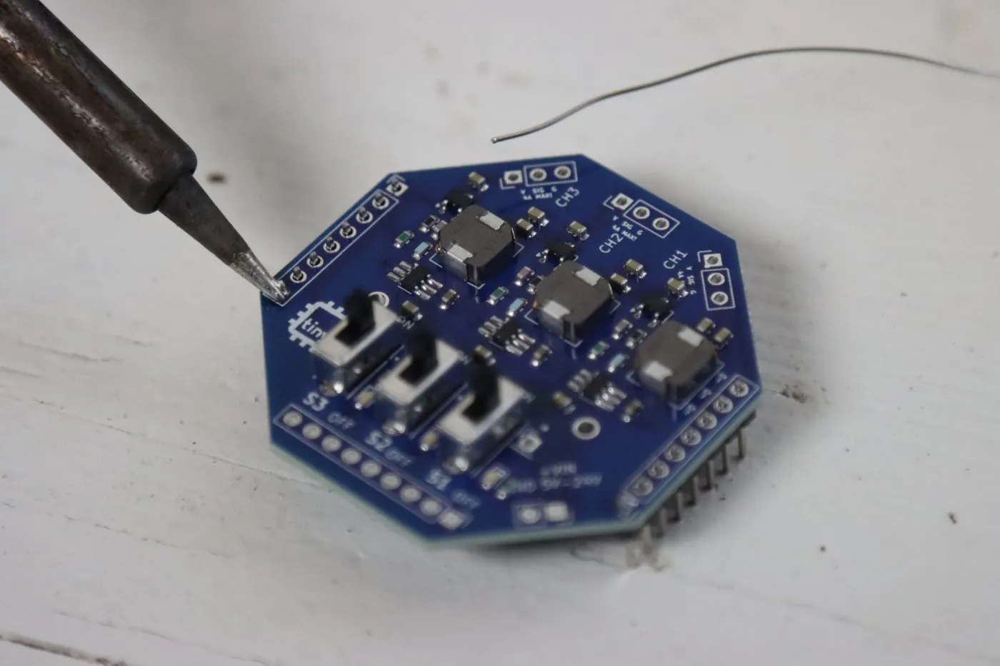
Solder the short pins on the top side of the tinyGlow. Tack one pin on each header first to lock everything in place, then go back and do the rest.
-
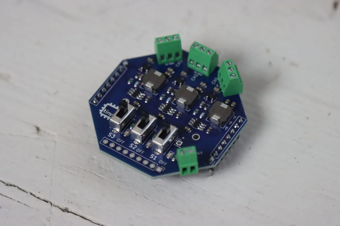
Now the screw terminals. Drop the three 3-pin terminals into CH1, CH2, and CH3, and the 2-pin terminal into the +VIN / GND spot. Point the wire openings outward, toward the edge of the board, or you’ll be trying to shove wires in sideways later.
Flip the board over and solder them from the bottom. These pins carry a lot of current, so make every joint a nice full cone of solder.
-
Look over your joints, then press the tinyGlow onto the tinyCore. It should be snug but shouldn’t need force.
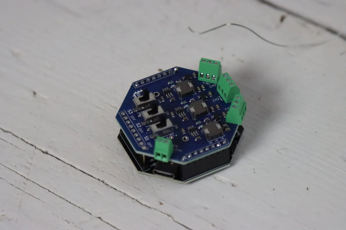
That’s the basic build. Now you need to decide how you’re powering it.
2. Pick Your Power
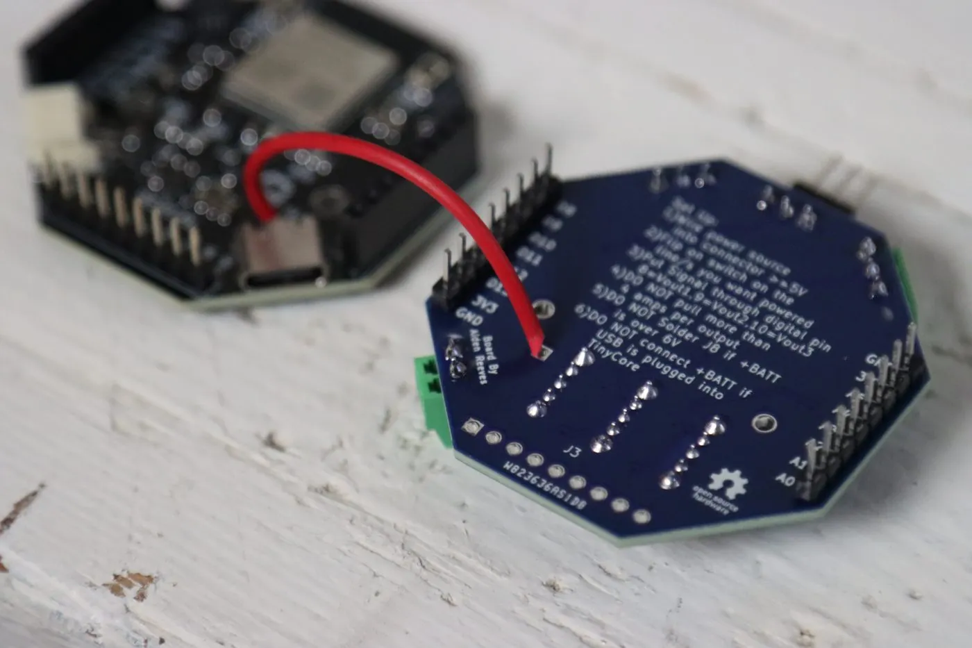
Section titled “2. Pick Your Power”Flip the board over. The setup instructions are printed right on the back, along with a few DO NOT warnings. Read them. They’re there because each one of them will cook something.
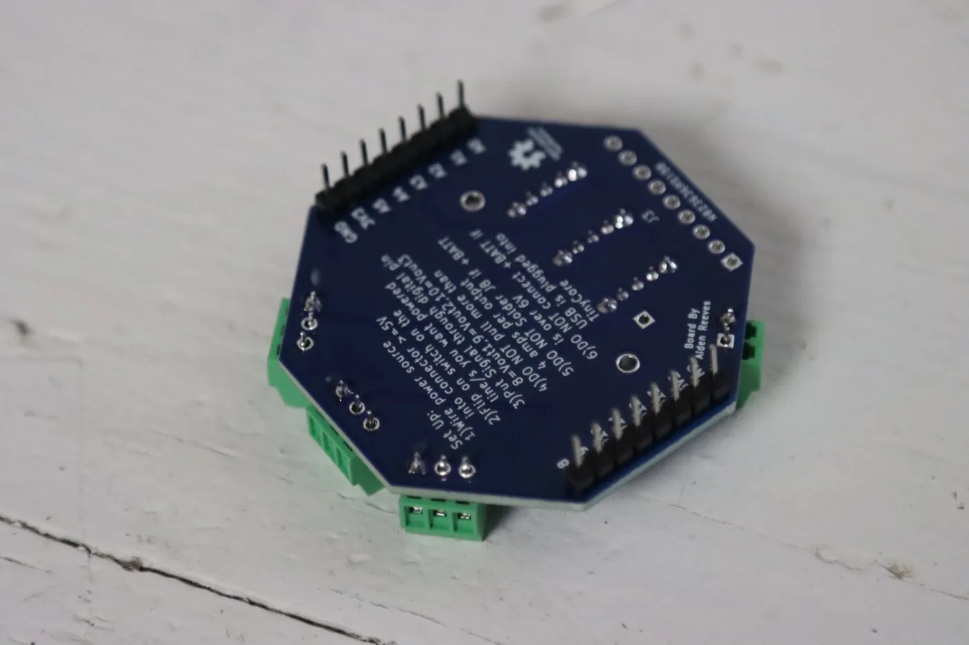
There are two ways to power tinyGlow, and you pick based on how many LEDs you’re running.
Option A: External power (most projects)
Section titled “Option A: External power (most projects)”Wire a power supply between 5V and 24V into the +VIN and GND terminal. Your tinyCore still gets powered and programmed over USB like normal. This is how you run long strips, or anything you want bright.
Don’t solder J8 if you’re going this route with anything over 6V.
Option B: USB power through J8 (short strips)
Section titled “Option B: USB power through J8 (short strips)”If you just have a short strip and don’t feel like dragging out a power supply, you can power the whole thing from the tinyCore’s USB port. That takes one extra wire, from the 5V pad on the tinyCore to the J8 pad on the tinyGlow.
This is what we used for the strip in the Example Code.
-
Push one end of the wire through the 5V hole next to the USB-C port on the top of the tinyCore.
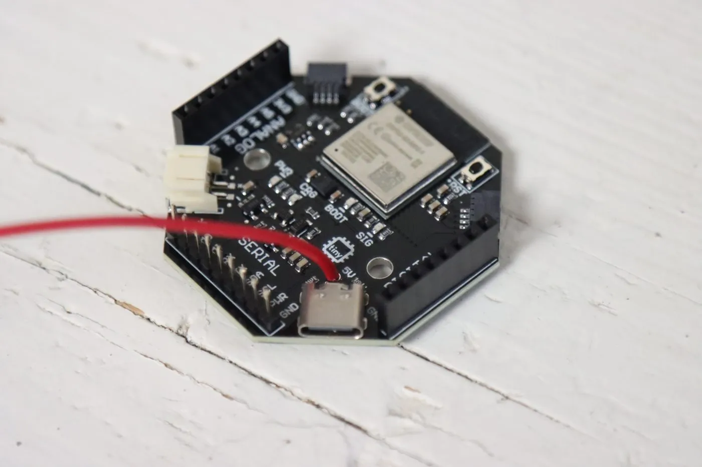
-
Flip the tinyCore over and solder it from the bottom.
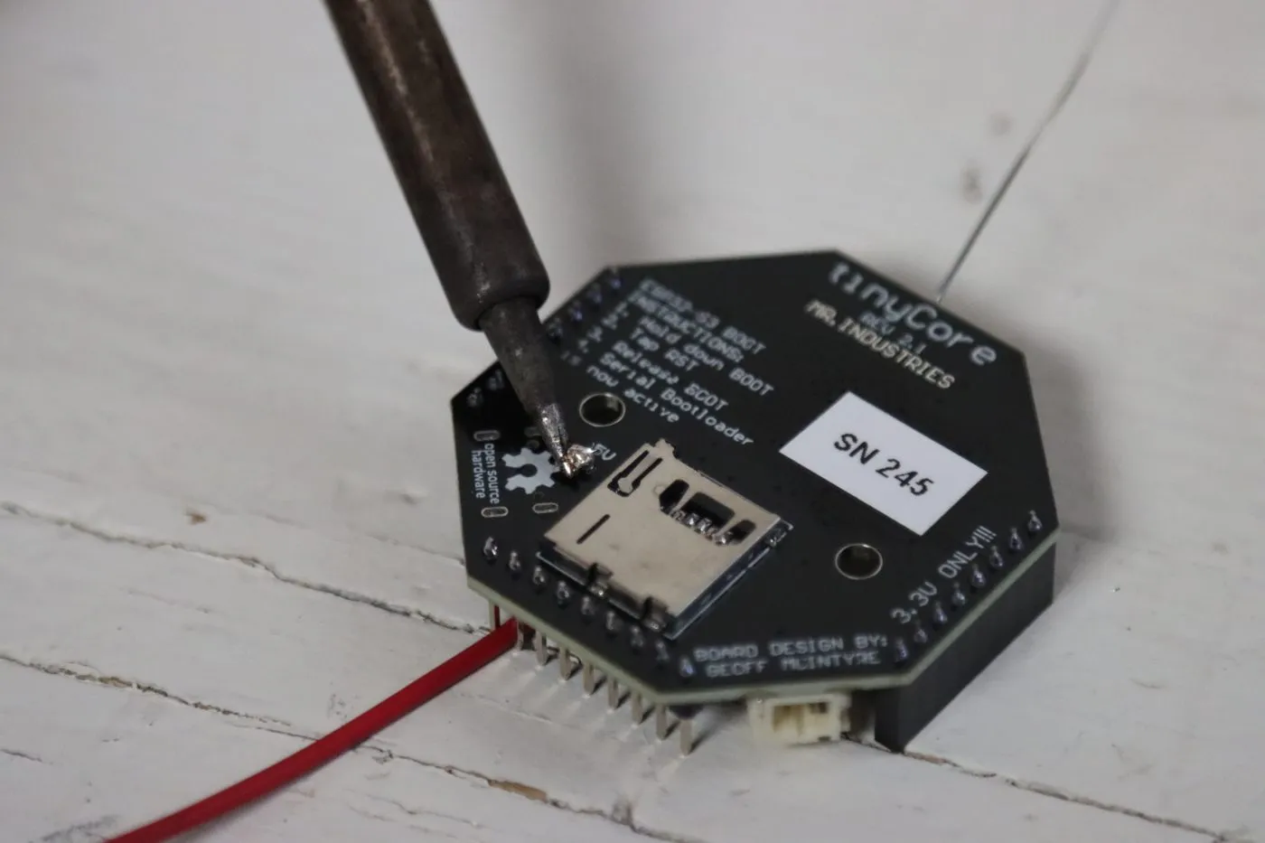
-
Feed the other end up through the J8 pad on the bottom of the tinyGlow (the square pad next to “Board By Alden Reeves”), then solder it on top. Leave enough slack that the two boards can still stack.
-
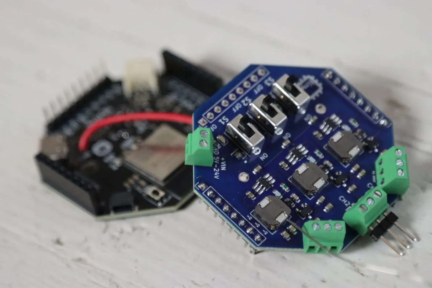
Stack them back together, tucking the wire in between.
3. Install the Library
Section titled “3. Install the Library”Every example uses FastLED, which handles that tight data timing for you.
| Library | Used By | Author |
|---|---|---|
| FastLED | All examples | Daniel Garcia |
Install it through the Arduino IDE Library Manager (Sketch > Include Library > Manage Libraries…) or the Libraries tab in the left sidebar, and search for “FastLED.”
4. Hook Up a Strip
Section titled “4. Hook Up a Strip”Every channel terminal is labeled V, SIG, and G:
- V is power for the strip
- SIG is the data line (from tinyCore pin 8, 9, or 10, depending on the channel)
- G is ground
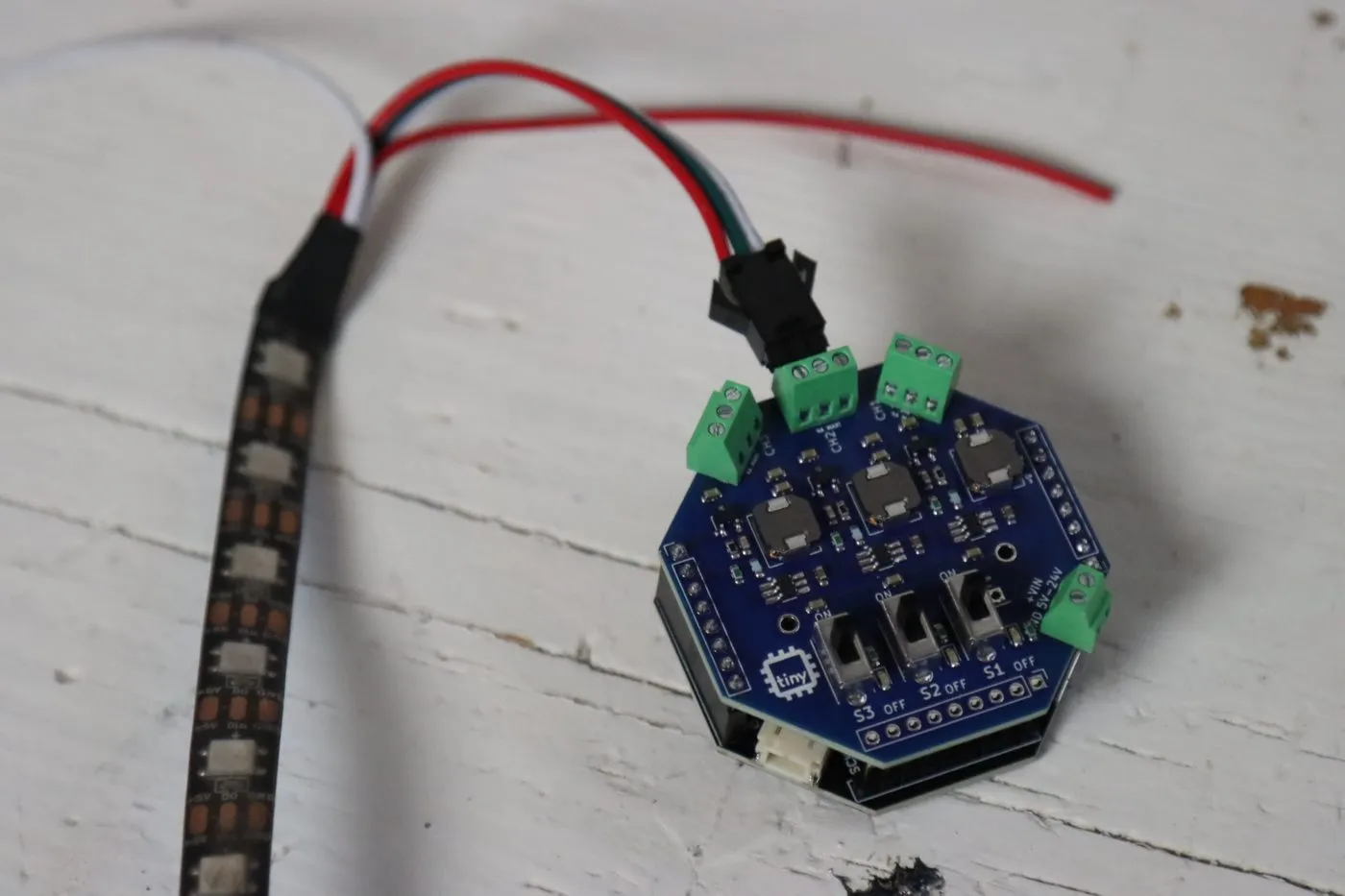
On most WS2812B strips that’s red to V, green to SIG, and white to G. Wire colors aren’t actually a standard, though, so check the labels on the strip itself (+5V, DIN, GND) before you trust the colors.
Loosen the screws, slide the wires in, tighten them back down, and give each wire a little tug to make sure it’s actually held. Then flip that channel’s switch to ON.
Head over to the Example Code and light it up.
Troubleshooting
Section titled “Troubleshooting”Nothing lights up at all. Start with the obvious stuff. Is that channel’s switch on? Is its status LED on? Did you wire the DIN end of the strip, not the DO end? Does LED_PIN in your code match the channel you plugged into (8 for CH1, 9 for CH2, 10 for CH3)?
The colors are wrong. I asked for red and got green. Your strip uses a different color order. In the FastLED.addLeds line, change GRB to RGB (or try the other combinations until red is red).
Only the first few LEDs light up. Your NUM_LEDS is set lower than the number of LEDs on your strip. Count them and update it.
The LEDs are flickering, or random ones show the wrong color. Usually a loose ground or a loose data wire. Check your screw terminals. If you’re running a long strip, it can also be the power sagging toward the far end, so try lowering the brightness.
The colors turn orange or brown toward the end of a long strip. The strip’s thin copper traces drop voltage over distance, and the blue LEDs give up first. Run a second pair of power wires to the far end of the strip (that’s what the extra red and white wires on most strips are for).
The tinyCore resets or disconnects when the LEDs turn on. You’re pulling more current than USB can give. Lower BRIGHTNESS, use fewer LEDs, or move to external power.
The board gets warm. A little warmth from the regulators is normal under load. Hot is not. Stay under 4A per channel.