How to Control LEDs with the tinyCore
Ready to light things up? Let’s start with the classic “Hello World”1 of electronics: Blink!
We’ll start by learning how to flash the built-in LEDs, dim the lights with PWM2, and then move up to controlling external ones!
Part 1: Blink the Onboard LEDs
Section titled “Part 1: Blink the Onboard LEDs”Your tinyCore already has two built-in LEDs:
Section titled “Your tinyCore already has two built-in LEDs:”-
LED_BOOT (connected to GPIO21) - Usually indicates boot or error status
-
LED_SIG (connected to GPIO33) - General purpose signal LED
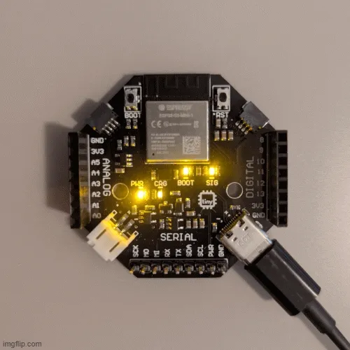
Let’s start by them. No wiring required!
Basic Blink Program
Section titled “Basic Blink Program”Copy this code into your Arduino IDE:
Both LEDs on your tinyCore should now be flashing On and Off like the GIF above.
Alternating Blink Pattern
Section titled “Alternating Blink Pattern”Let’s try something more interesting. Replace your loop() function with this alternating pattern:
Now the LEDs should be taking turns blinking!
Part 2: PWM Control (Dimming and Brightening)
Section titled “Part 2: PWM Control (Dimming and Brightening)”The ESP32-S3 supports Pulse Width Modulation (PWM)3 for smooth brightness control. This will let us fade the LEDs in and out!
Smooth Breathing Effect
Section titled “Smooth Breathing Effect”You should see your LEDs fading off and on smoothly, almost like two fireflies! (or do you call them lightning bugs??)
Manual Brightness Control
Section titled “Manual Brightness Control”Another option is to manually set the LEDs to specific brightness levels:
Part 3: External LED with Breadboard
Section titled “Part 3: External LED with Breadboard”Now let’s add an external LED! The tinyCore has plenty of GPIO pins available for this.
You’ll need
Section titled “You’ll need”- Your tinyCore
- A breadboard
- A “Gumdrop” LED (any color)
- A 220Ω resistor
- Jumper wires (male-to-male)
??? question “Why do we need a resistor? Click for the Answer!”
Ohm’s Law states that the current through a device is inversely proportional to the resistance of that device. Put simply,a very small resistance equals a very LARGE current. LEDs have very little resistance, meaning we have to add a “current-limiting” resistor to protect them from getting fried!
We calculate the size of this resistor with a simple formula:
Where:
-
= Resistor value in Ohms
-
= Supply voltage (3.3V on the tinyCore)*
-
= LED forward voltage drop (typically 1.8-2.0V for red LEDs)
-
= Desired LED current (typically 10-20mA)
Example calculation for a red LED:
Lucky for us, 75 is a standard resistor value, but if it wasn’t, we’d round up to the next higher standard value, which is 100Ω. For extra margin of safety, 220Ω is commonly used and still provides good brightness while ensuring the LED won’t be damaged.
Available GPIO Pins:
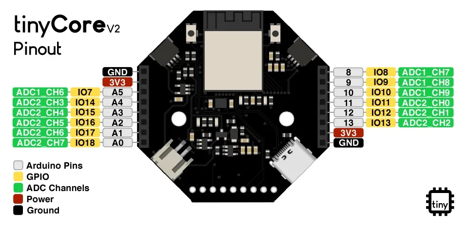
You can use any of the GPIO4: pins for your external LED (pictured in Yellow):
-
Digital pins: 8, 9, 10, 11, 12, 13
-
Analog pins: A0, A1, A2, A3, A4, A5
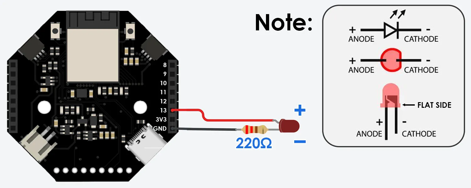
Wiring the External LED
Section titled “Wiring the External LED”Let’s use GPIO13:
- LED short leg (cathode) → Pin 13
- LED long leg (anode) → 220Ω resistor → GND Pin
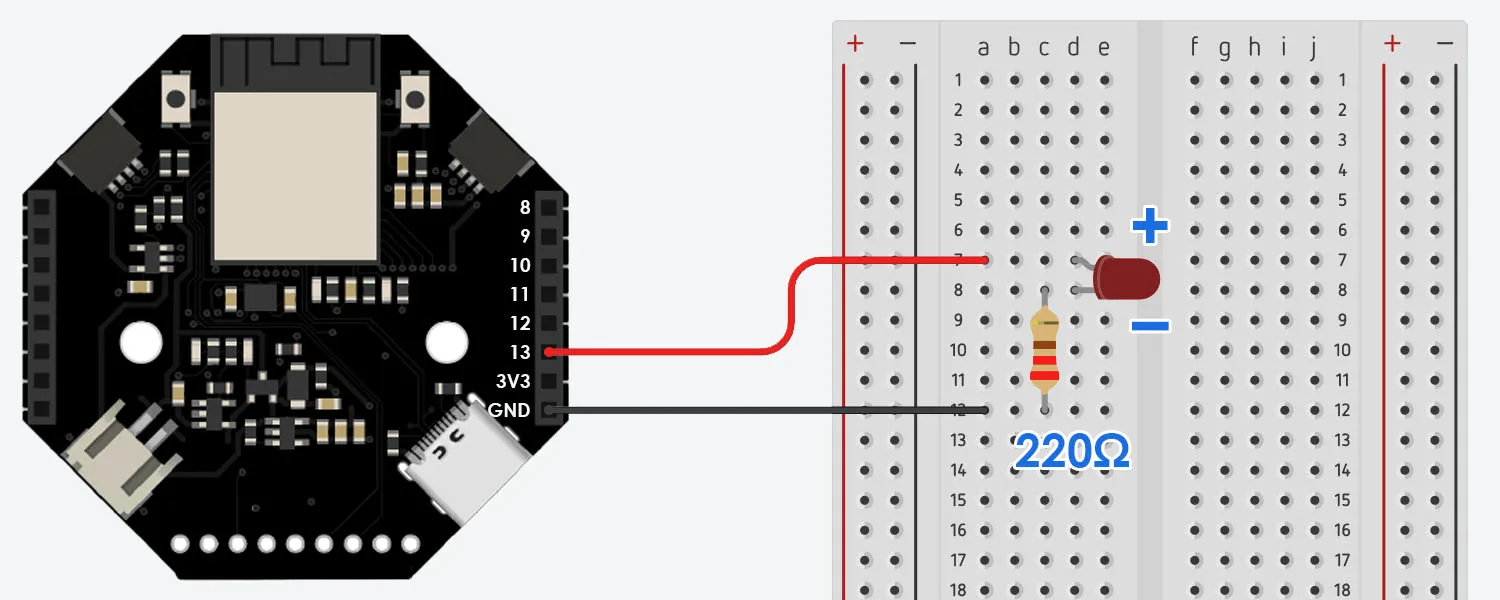
 And here’s the circuit on a breadboard:
Code for External LED
Section titled “Code for External LED”Now it’s time to program the tinyCore to blink this LED! Here’s the code:
PWM Control for All Three LEDs
Section titled “PWM Control for All Three LEDs”Let’s bring this whole thing home and control all three LEDs via PWM.
Understanding the Code
Section titled “Understanding the Code”Digital Control
Section titled “Digital Control”pinMode(pin, OUTPUT)- Sets a pin to output modedigitalWrite(pin, HIGH)- Sends 3.3V to the pin (LED on)digitalWrite(pin, LOW)- Sends 0V to the pin (LED off)
PWM Control
Section titled “PWM Control”ledcAttach(channel, frequency, resolution)- Configures PWM settingsledcWrite(channel, value)- Sets brightness (0-255 for 8-bit resolution)
delay(milliseconds)- Makes the program wait
Challenge Code
Section titled “Challenge Code”Spoilers Ahead!
SOS Signal
Section titled “SOS Signal”Troubleshooting
Section titled “Troubleshooting”External LED not lighting?
-
Check polarity - long leg (+) goes to Pin 13, short leg (-, flat side) to resistor, resistor to Ground
-
Verify your resistor value (220Ω, should be Red, Red, Brown, Gold/Silver)
-
Make sure connections are secure on the breadboard
-
Could be burnt out, try another LED!
LED is very dim?
Check your resistor value - too high resistance dims the LED (For a brighter light, try 150Ω resistor instead)
Error: ‘ledcSetup’ was not declared in this scope
This usually happens with code generated by AI. LLM’s tend to hallucinate outdated syntax for the ESP32 board library. ledcSetup was removed in v3.0.7 of Expressif’s libraries and combined into ledcAttach. Make sure you use the latest syntax!
What’s Next?
Section titled “What’s Next?”Now that you can control LEDs, you can control almost anything: Motors, buzzers, relays - they all use similar digitalWrite() commands.
Ready to try:
Footnotes
Section titled “Footnotes”-
In programming, “Hello World” refers to the simplest possible program that demonstrates basic functionality. New students will learn how to print the words “Hello World” in their specific programming language. ↩
-
PWM (Pulse Width Modulation) is a technique that rapidly turns power on and off to simulate different voltage levels. By changing how long the signal stays “on” versus “off,” we can make LEDs appear dimmer or brighter, even though they’re actually just blinking too fast for your eyes to see (thousands of times per second). ↩
-
Pulse Width Modulation is a technique that rapidly turns power on and off to simulate different voltage levels. By changing how long the signal stays “on” versus “off,” we can make LEDs appear dimmer or brighter, even though they’re actually just blinking too fast for your eyes to see (thousands of times per second). ↩
-
“GPIO” stands for General Purpose Input-Output. While labeled as “Digital” and “Analog”, all GPIO pins on the tinyCore can actually do both! (with some caveats). The labels simply indicate their primary intended use. ↩